Data Fabric
The Data Fabric acts as a bridge between API data and the user interface, processing and formatting data for seamless integration. Before drawing a diagram, you must create an artifact as the foundation for your design.
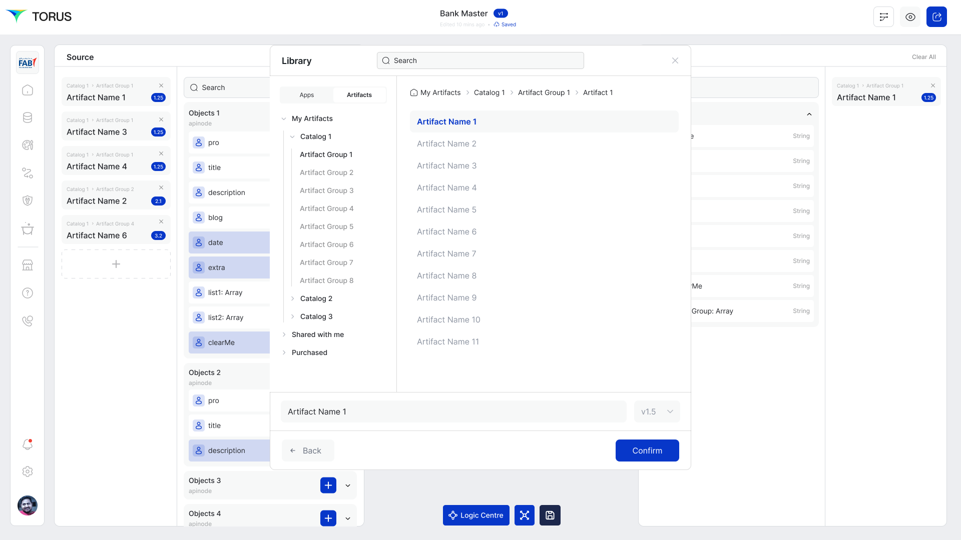
Creating a New Artifact
- Navigate to 'Select artifact' > 'My Artifacts' > 'App Group' > 'App Name'.
- Click on 'Create Artifact' to define your workspace.
- The artifact serves as the base for defining and structuring the Data Flow Diagram (DFD).
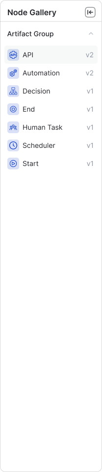
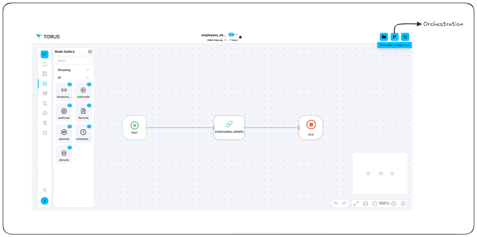
Node Gallery
The Node Gallery provides key building blocks for data processing pipelines. Each node type serves a specific function:
| Node | Description |
|---|---|
| startnode | Marks the beginning of a workflow. |
| endnode | Marks the termination of a workflow. |
| streamnode | Processes real-time data from sources like Kafka. |
| apinode | Manages data interactions with APIs. |
| schedulenode | Automates scheduled tasks. |
| filenode | Handles data stored in files. |
| dbnode | Connects and interacts with database systems. |
Each node requires property configuration, accessible through a right-click.
Steps to Create a Data Processing Workflow in Data Fabric
Draw Diagram (Data Processing Flow)
-
Open the Data Fabric workspace.
-
Use the Node Gallery to select and drag data processing nodes onto the canvas.
-
Available nodes include:
streamnode(for streaming data)apinode(for API data)schedulenode(for scheduled tasks)filenode(for file data)dbnode(for database data)startnode(default start node)endnode(default end node)
-
Arrange and connect the nodes to define the data processing flow.
-
Configure the properties of each node (e.g., API endpoints, database connections, file paths).
-
Remember that the startnode and endnode do not require configuration.
Configure Events and Rules (Logic Center)
- Open the Logic Center.
- Navigate to the "Rules" tab.
- Define data processing rules using the Rule Engine or custom JavaScript in the Expression editor.
- Navigate to the "Actions" tab, specifically the "Events" section.
- Use the left-side menu to select the artifact and specific nodes or their properties.
- Add events to be emitted from data processing nodes.
- Define how these events will push data to queues (e.g.,
"Success","Failure","Suspicious"). - Set custom statuses for more granular event handling.
Set Orchestration
- Click the "Orchestration" icon (top-right corner).
- Map source data to target data.
- Transform data as needed (e.g., rename fields, create combined fields).
- Ensure data flows correctly between the data processing nodes and other systems (UI Fabric, external APIs).
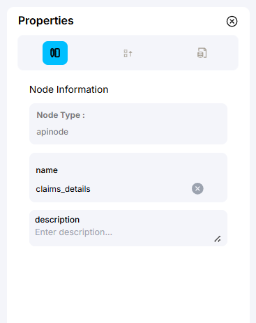
Configuring Node Properties
Each node has configurable properties available in the "Node Properties" panel.
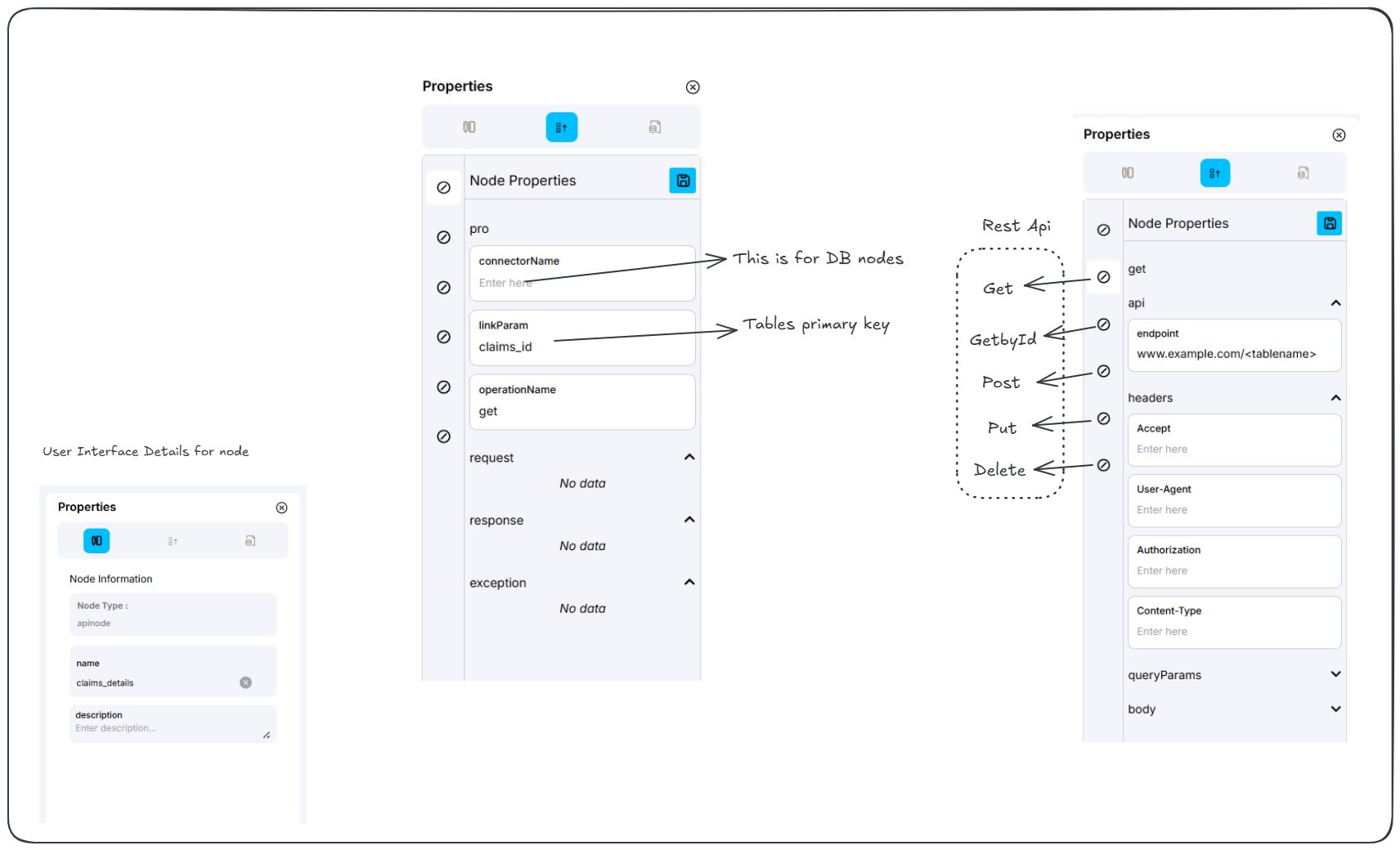
| Property | Description |
|---|---|
| connectorName | Defines the database connection (for dbnode). |
| linkParam | Used for linking parameters (e.g., primary keys). |
| operationName | Specifies the API operation (e.g., get). |
| Request, Response, Exception | Allows viewing or modifying request, response, and exception handling. |
| Node Information | Displays details such as node type (apinode), name (claims_details), and description. |
HTTP Method Selection
The apinode supports multiple HTTP methods:
- Get
- GetById
- Post
- Put
- Delete
Each method has a toggle switch (0) to enable or disable it.
Once the workflow is drawn and properties are configured, additional customizations are required, including security settings, event triggers, rules, and custom code.
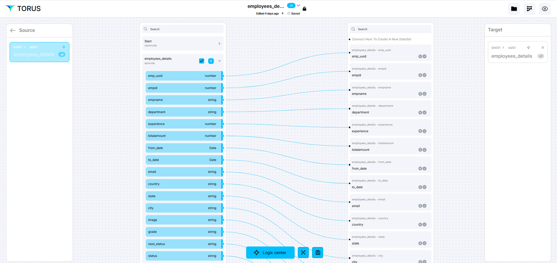
Data Mapping
Before designing a workflow, an artifact must be selected or created.
Once an artifact is selected:
- Establish data mappings by connecting fields from the Source to the Target.
- Drag a link from a field in the Source column to the corresponding Target field.
Logic center
The Logic Center allows advanced configuration of Security, Events, Actions, Rules, and Custom Code (SEARC).
SEARC Breakdown
| Component | Function |
|---|---|
| S - Security | Manage access and authentication. |
| E - Events | Define triggers for actions. |
| A - Actions | Specify operations for data processing. |
| R - Rules | Implement conditional logic. |
| C - Code | Add custom scripts for advanced tasks. |
Once inside the design workspace, locate the 'Logic Center' button at the bottom.
The Logic Center enables setting actions and security at both:
- Node Level
- Field Level (within Source or Target data)
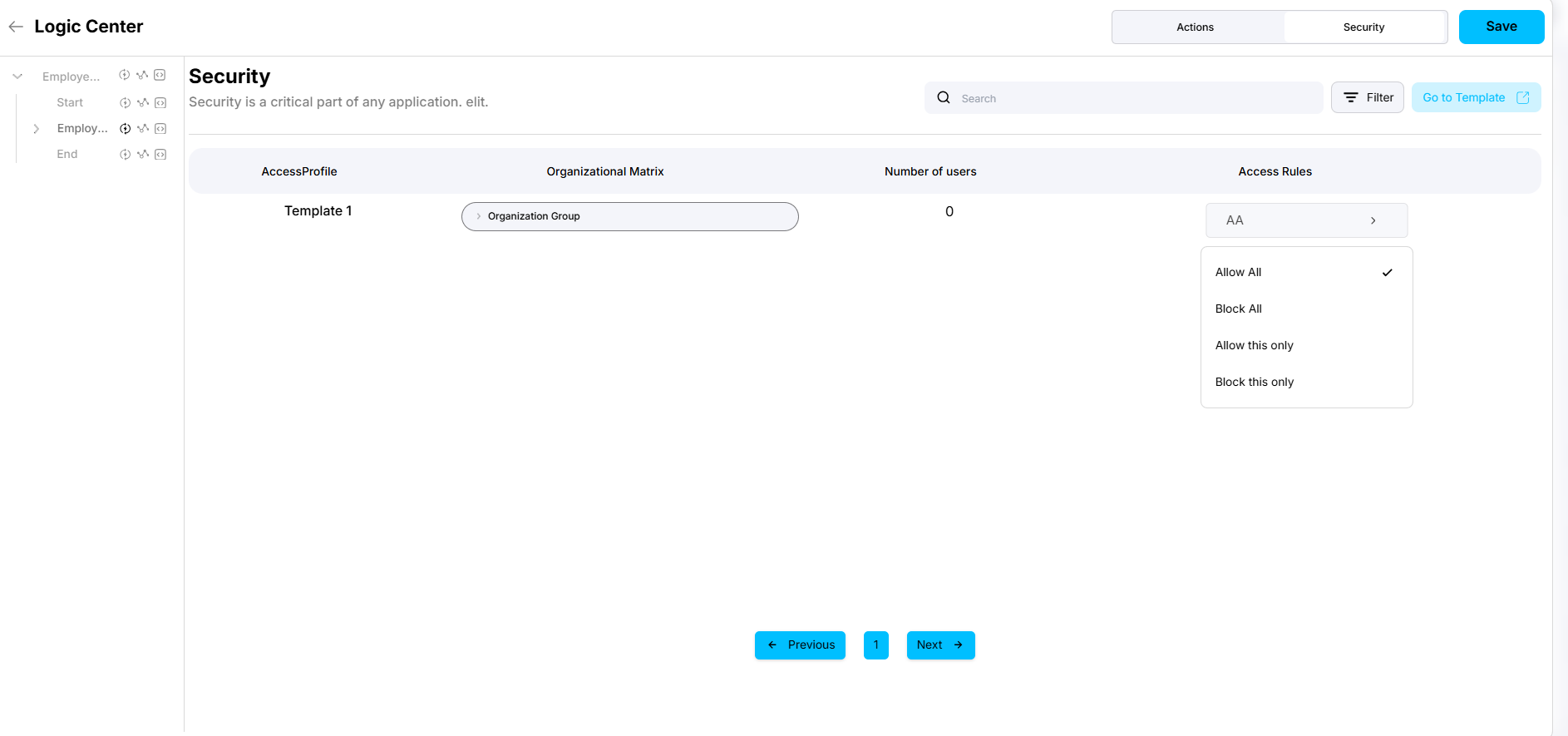
Setting Up Security Rules
- Open the Logic Center.
- Navigate to the Security tab.
- Select a Source Node (e.g.,
employee_detail). - Choose 'ALLOW ALL' to grant unrestricted access.
Configuring Actions & Events
- Open the Actions tab in the Logic Center.
- Define actions such as:
- Lock and TTL
- Pagination (for UI nodes)
- Configure Event Triggers:
- Success
- Failure
- Suspicious Activity
- Custom Status (format:
API<Value>)
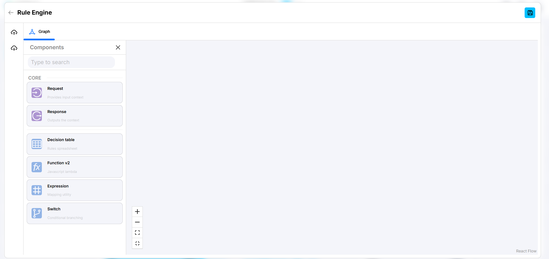
Defining Rules
Rules control how data is processed. There are two ways to configure rules:
Rule Engine (Visual Builder)
- Provides a drag-and-drop interface for defining logic.
- Useful for non-technical users.
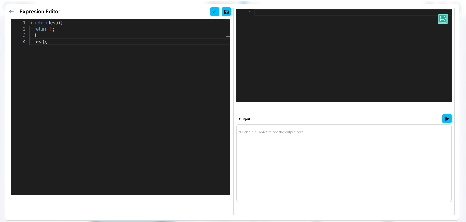
Code Editor (Custom JavaScript)
- Allows writing custom JavaScript logic for advanced processing.
- Supports complex rule sets.
Final Steps
- Configure all necessary nodes, mappings, and logic.
- Save your workflow.
- Run a test deployment to validate functionality.
Always click "Save" after making any changes to ensure updates are stored successfully.